Little projects have a habit of growing into more complicated endeavors. As mentioned in a previous post, it was thought that a simple remote monitoring system for the backup battery and repeater environmental conditions would be a useful addition.
It was decided that battery voltage, DC supply voltage, battery temperature and ambient (cabinet) temperature would adequate. A small DAQ hung off the Pi3B+ being used as the AllStar controller with 10-12 bits resolution should do the job.
A little research revealed inexpensive ADS1115 4 channel I2C bus A/D converter boards that were available for less that ten dollars. These can operate on either a 3.3 or 5V single rail supply, require just two I2C connections to the Pi’s GPIO bus, and offer 16 bits (15 bits + sign bit in single-ended mode) of resolution. These boards were designed with the Arduino in mind, but they work just fine on the Pi as well. Sample code in both Python and C was available as a starting point for the software end. A couple of boards were ordered.
As far as temperature measurement, 3 terminal band-gap sensors like the LM35 and TMP series (TMP35,36.37) are easy use and require no calibration. They operate on a single 5V supply and output a voltage linearly proportional to temperature in degrees C. Several TMP37 sensors were purchased. These measure temps from 5C to 150C and output 20mv/degrees C. Just measure the output voltage and divide by 0.02 and you have the temperature in Centigrade degrees.
The ADS1115 has an internal programmable gain amplifier that allows scaling the input voltage range. This setting, along with the the supply voltage (5V or 3.3V) determines the full scale value (for a 32768 count) of the converter. It was decided to use a 5V supply and 0-4.096V full scale for the best noise immunity. A 10:1 input voltage divider built with a few precision resistors would allow 0-40V DC voltages to be monitored. Because the Pi I2C bus uses 3.3V logic levels and the ADS1115 is powered by 5V, a level translator is included in the design to insure compatibility without having to modify pull-up resistors.
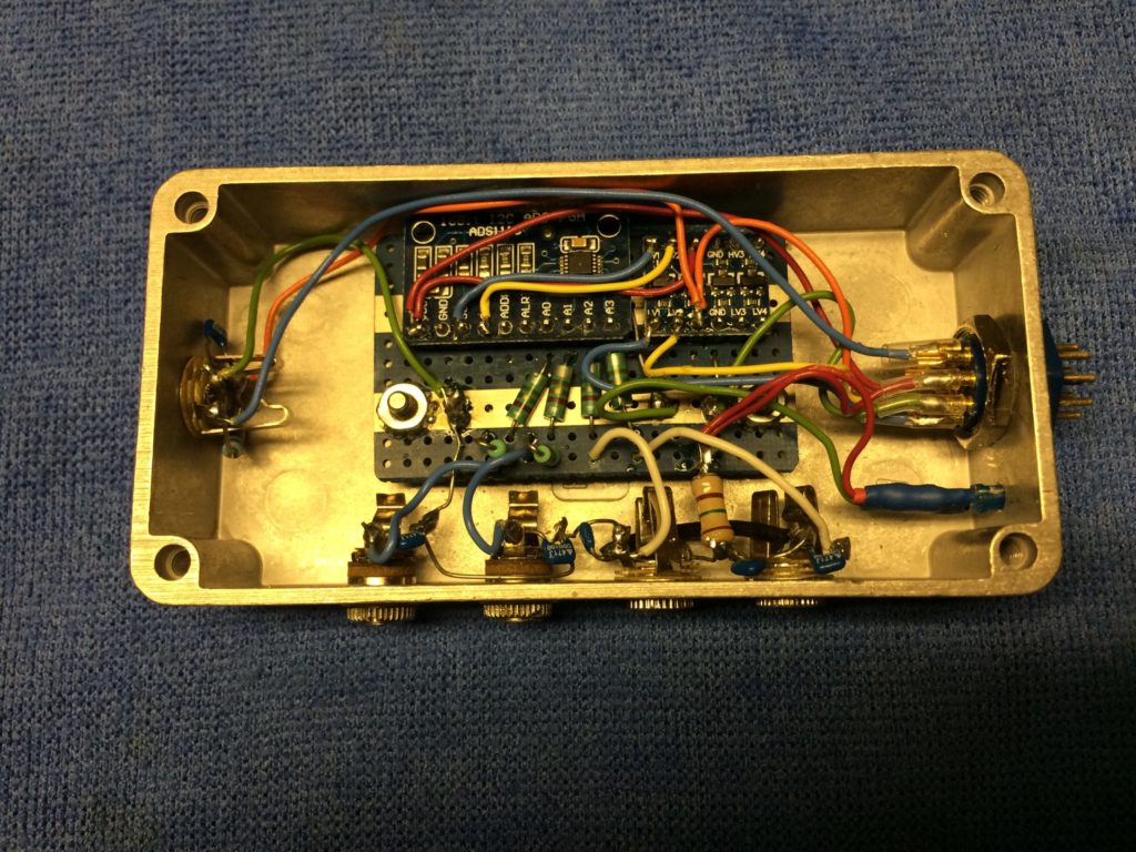
A prototype was assembled in a die cast metal box for shielding. LC low pass filters were incorporated on each input using 0.5uH RF chokes and 470 pF ceramic caps to minimize RF ingress. Sample software was modified for some testing. It was set up for two voltage channels and two temp channels on the four inputs available with the 1115 ADC.
The two voltage channels worked great. The resistors in the voltage divider present a moderate 200K input resistance and were hand-selected within about a few tenths of a percent. The readings are formatted in the software for two decimal places as in “13.45”, and the measured voltage closely agreed with a 4-1/2 digit multimeter. A little UHF RF was sprinkled in the vicinity with a HT, and all was well. Voltage measurements: done.
The temperature channels were a different matter, however. It turns out the TMP37 sensors are exquisitely sensitive to RF. Thus began the long saga. I tried just about every RF trick in the book to tame these sensors. The manufacturers’ datasheet recommends a 0.1uF ceramic cap from Vcc to ground. In high noise environments they also suggest adding an additional 1-5uF tantalum cap in parallel. RF ingress at various frequencies vs noise is not specifically addressed in the datasheet. I tried those suggested caps, and several other bypass capacitor combinations with disappointing results. A 4 watt 70cm HT set to 1 watt on 446 MHz was used as the test transmitter. With the prototype sensor isolated on the bench, transmitting from 3 meters away would upset the reading by the equivalent of several degrees C. At closer range, the reading were less than plausible and clearly in error with ridiculous values. It was obvious the band-gap diode in the sensor made a dandy detector and was rectifying the RF and causing a DC offset. Back to the drawing board.. Round two explored shielding; this included installing the sensor in a closed-ended brass tube with a well shielded connecting cable wrapped in copper tape at the entrance of the tube. Better, but still not good enough. I have had radio receivers that were less sensitive to RF than these sensors!
Round three added UHF rated ferrite beads to the Vcc and output leads of the device . Slightly better still, but the repeater site is a very high RF environment and my confidence was low.
PLAN B: After some discussion, a friend suggested trying a 1 wire temperature sensor. I thought that they likely used a diode type sensor, and just have an internal A/D and 1 wire interface. Might have the same RF issues as the 3 wire sensors that are driving me crazy.
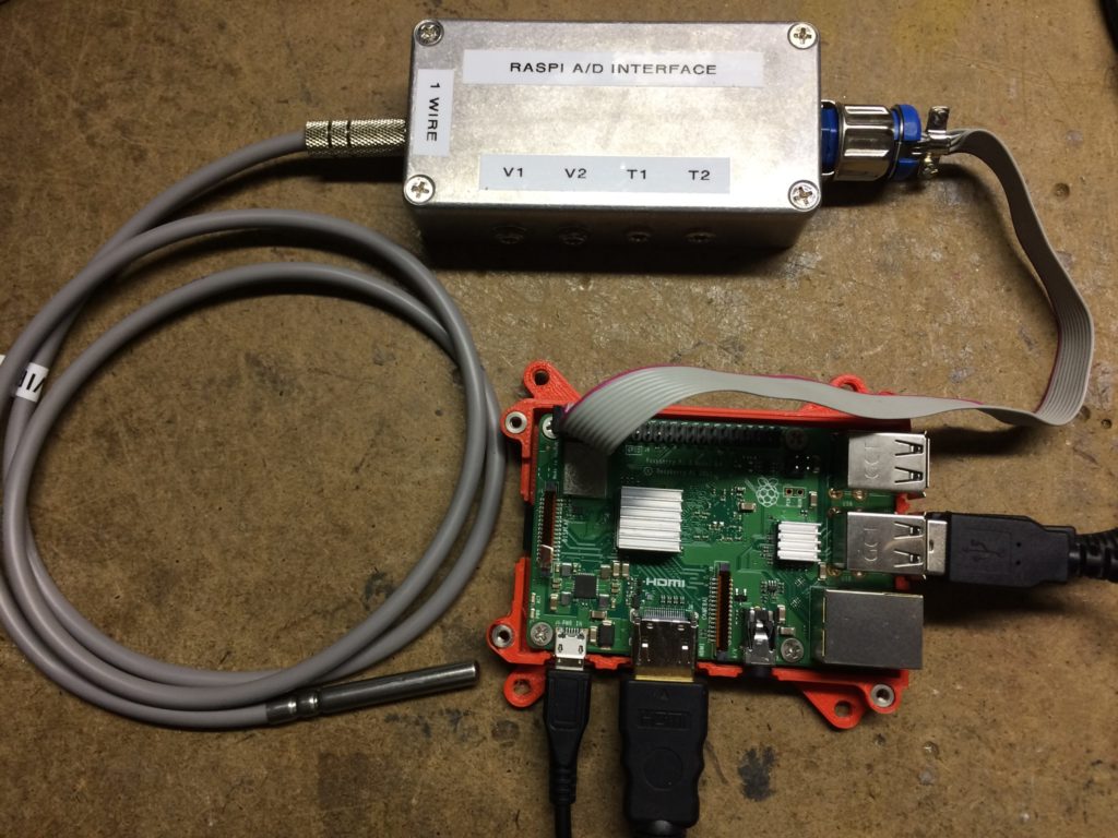
Two very nice 1 wire stainless steel temp probes with silicone wire leads were ordered from Jeff B. (Amazon) as a trial. The 1 wire GPIO kernel driver was loaded on the Pi and some new software coded. When the probes arrived, expectations were subdued, but the tests proceeded. Amazing. These things seem to ignore RF; even at close range. Even TX at 4W power from the HT at less than 1 meter distance was OK. Problem is most likely solved. A new hole for another jack was drilled in the die cast box to accommodate the new 1W temp probe. Luckily, there was a spare wire in the cable available to make the connection to GPIO #4 on the Pi.
Thanks to some ideas gleaned from a sample script written by WA3DSP, I was able to pipe the output from the compiled C binaries that read the voltage and temp data into the AllStar TTS voice synth. Some custom ulaw sound files were created that say things like “the battery voltage is”, “the battery temperature is” and a few others. Now, on demand, with a DTMF commands over AllStar, spoken battery voltage and temp, supply voltage, and ambient temperature readings can be executed.
Next step is to make a trip to the site and do the physical install. A longer connecting cable to the Pi’s GPIO bus was constructed to replace the short test cable. Plan is to mount the A/D box in the rear of the cabinet about 75 cm from the Pi. How long can you go with a I2C bus signal? Well I found a nice paper on that. It depends on the clock speed of the bus. The speed can vary; typically from 10K to 1M baud. At the default 100K speed, the main limiting factors are capacitance to ground and termination resistance. With the standard Pi hardware, a good rule of thumb is 500 pF max on the capacitance. I used 6 conductor foil shielded cable 75cm long. It measured an average of 180 pF from any conductor to the foil shield, and about 100 pF inter-conductor. So this length should be fine. I didn’t dig out the scope and look at rise and fall times yet, but if I2C errors are noticed the clock rate can easily be decreased with a config.txt argument. More clamp ferrites were added to the connecting cable to keep away evil spirits. BTW, If really long distances are needed, special I2C transceiver driver chips are available. They are used on both ends of the long interconnect.
EPILOG: As a final TMP37 temperature sensor experiment, a new (last!) configuration was tried. A small, fully shielded aluminum box was liberated from the junk box. A piece of proto PCB was used to mount the sensor along with more 0.5 uH LP/470 pF cap filters in the Vcc and output leads. Three bypass caps were installed close to the leads on the device, along with the ferrite beads. The sensor was taped to the bottom of the box with aluminum tape to thermally bond and electrically double-shield the device itself within the shielded enclosure. Finally, a double shielded 3.5mm plug to 3.5mm plug cable, again with a ferrite, was used to make the connection to the A/D box. Yes, it mostly works with RF. If one gets the HT antenna within about 25cm of the connecting cable, it starts to affect the reading slightly. But that’s a really strong field. I’m going to try this sensor for ambient temperature at the site and see how it works. It’s optional, and not a critical reading. If the TMP37 proves useless at the site, and the ambient temp parameter proves valuable, plan C will implement another 1 wire sensor for this reading as well.
Yet another interesting part that I may try for ambient measurements, which is inching it’s way to me on a slow boat from China (eBay), is the Bosch BME280 combination temp, barometric pressure and humidity sensor with I2C and SPI bus interfaces. We don’t really need the additional parameters, but why not? RF stability? Who knows. It’s in a tiny metal can, so maybe.. Update in a few months when they finally arrive.
As a point of reference, I had a package out for 84 days from China recently. Ordered on Feb 26, and arrived today 5/20. A lot of low priority freight that normally used air transport is being sent by sea due to the pandemic.
Dave, K7DMK