Our original AllStar link controller used a 1u rack mount mini-server utilizing a dual core Atom CPU and a SSD. It was running the Acid Linux distro based on CentOS. The radio interface was a DMK Engineering URI. Also mounted in the rack was a pull out LCD monitor keyboard mouse. It worked OK for several years, but Acid/CentOS 5.xx is getting long in the tooth, with no current support.
We experimented with Raspberry Pi based controllers starting with the Pi2. The audio was a sometimes a little choppy compared to the Atom CPU. With the advent of quad-core Pi’s that problem went away completely. For quite awhile, we ran a Pi3B+ in a 3D printed case sitting on top on the Quantar card cage along with the URI and cables. It worked, but wasted rack space and the Pi ran pretty hot.
Looking at the 70cm Quantar one day, it was realized there was a nice place to put an AllStar controller behind the blank filler plate between the receiver and system control module. In the 800/900 MHz machines this slot is often occupied by a high-stability frequency reference. On other bands, occasionally, a secondary receiver is installed in the space for special applications, or perhaps a SAM (station access module). In the 450 repeater we have, it’s empty.
We had been evaluating some of the new CM4 compute modules from the Raspberry Pi Foundation mounted on their CM4-I/O board. This setup has several advantages when building a repeater controller. One problem with the standard Pi is the fact that you need access to 3 of the 4 sides of the board for connections and SD card. It becomes an unwieldy porcupine making it difficult to neatly mount in a rack case, particularly if you need external connections to the I/O. A nice thing about the CM4-I/O board is all the connectors including the microSD, are on the back edge.
The CM4 modules snap on to the I/O board in a parallel fashion using 2 low profile 100 pin PCB-PCB connectors. This is big change from the older compute module 3’s that plugged in using an edge connector like a memory DIMM. The CM4’s are available in many models with varying amounts of DRAM, with/without WiFi/Bluetooth, and eMMC flash storage. They all share the same form factor and are interchangeable and therefore upgradeable. The CPU of the CM4 is a faster quad-core@ 1.5GHz BCM2711 vs the 1.2 GHz SOC of the regular Pi4. There is one downside of the official Raspi Foundation CM4/IO board arrangement. Much of the available bus bandwidth is channeled to the single lane PCIe expansion slot present, this eliminates the USB 3.x connections as compared to the Pi4. In this application it does not matter. The URI, and all the other AllStar radio interfaces so far are USB 2.0 only, AFAIK. The sample rates used for ROIP audio simply does not require USB 3. There are other third party CM4 I/O boards available that lose the PCIe slot and offer the bandwidth to USB 3.x connections. But again, not needed here.
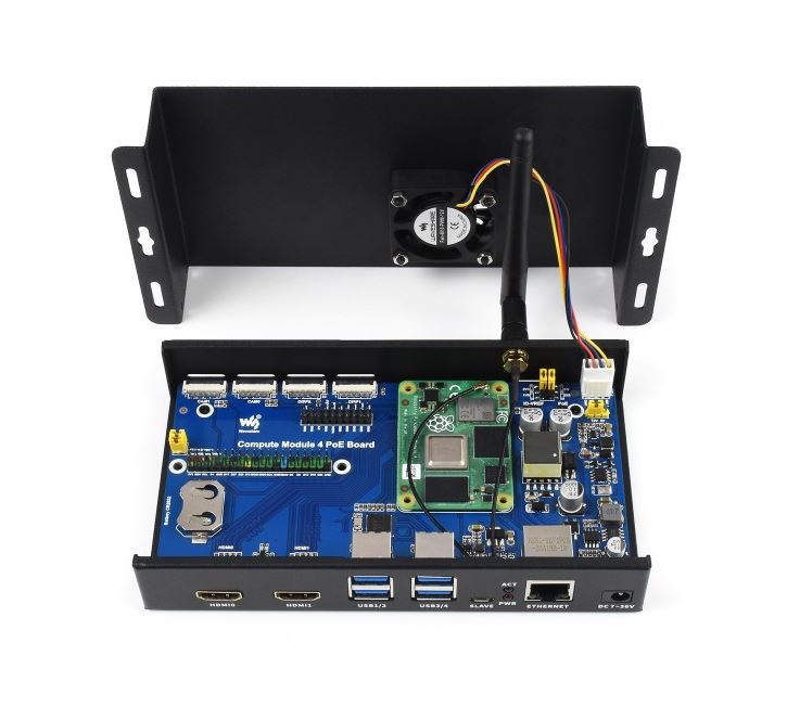
WaveShare makes a very nice all-metal case that fits the I/O board with the installed CM4 module. It has a CPU fan to cool the processor and is inexpensive. Ideal for this application. The added RF shielding is also welcome. The Waveshare CM4 version of an IO board (not used in this project) is shown mounted in their case in the photo below. The small green solder mask PCB is the CM4 compute module. This particular CM4 variant has the Wifi/Bluetooth module as well as eMMC onboard.
If USB 3 is really needed, this I/O board has it instead of PCIe. There are more and more versions of these CM4 I/O boards becoming available. The Raspberry Pi Foundation has made the design open source along with the PCB files. Custom spins of the board can be made pretty quickly.
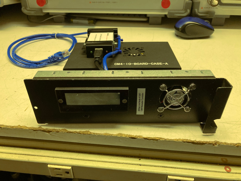
To build our new controller, we started with a blank Quantar cover plate from eBay, some 0.062 aluminum sheet, aluminum angle, and scrap plexiglass. A 1GB CM4 module with 8GB of eMMC flash and no WiFi was selected, and AllStar installed on the eMMC drive. The CM4 module was mounted on the CM4-I/O board which in turn was installed in the WaveShare case. A few 5/8 holes were punched in the side of the WaveShare cover for added air flow, and a bracket was fabricated to hold the URI to the top of the case. There is just enough clearance inside the repeater for the URI to be stacked on the WaveShare enclosure when it’s mounted to the aluminum plate.
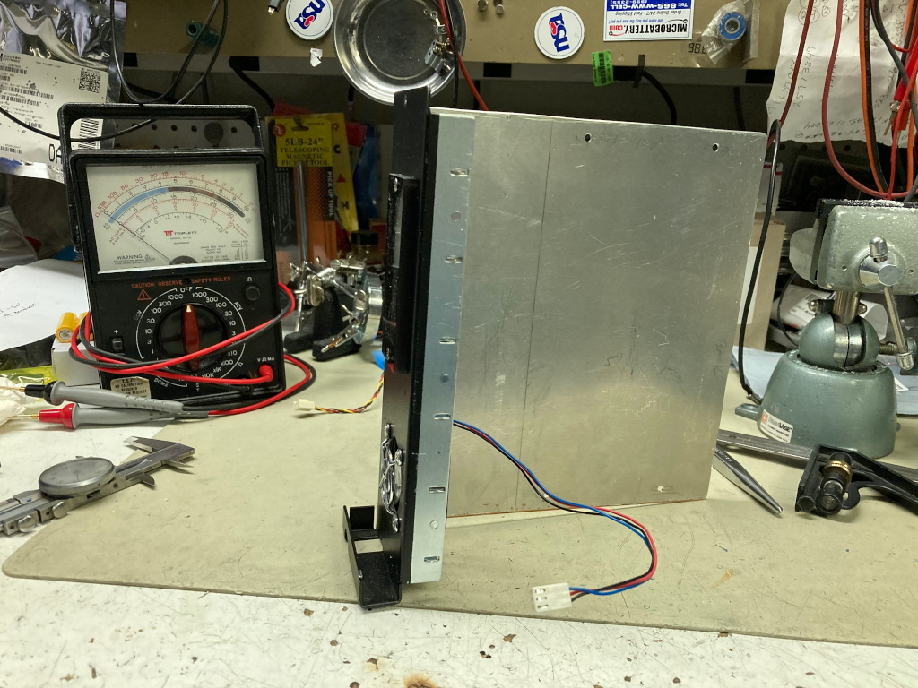
Mechanically, the aluminum plate is cut to just under 8.25 inches high and mounted to the blank cover plate with 1/8 x 1/2 aluminum angle. The assembly slides into the card cage just like an official Moto module. A 40mm cooling fan with a finger guard is mounted in the cover plate. A small Plexi window with a cutout was installed to allow observation of the LED’s on the I/O module and URI. The WaveShare case and URI are positioned so their LED’s face forward. The URI to repeater, cat5 Ethernet, and DC power cables pass out through an opening in the rear of the card cage. The CM4-I/O board has a build-in switching regulator to allow 12 volt operation. We are using a fairly reliable PhiHong brand 2.5A 12V cord lump supply for controller power. The I/O board can also be setup to do POE if desired. As an aside. we have found over the years that these AC switching adapters are NOT all created equal. Many, many are unsafe, unreliable garbage with terrible components, poor performance and bad construction. Failure rates typically are very high, even after just a few months of use, and some pose real safety/fire hazards. Higher quality units are made by I.T.E., Meanwell, PhiHong, Delta, Panasonic, Sony and a few others. They cost more, but are worth it in the long run.
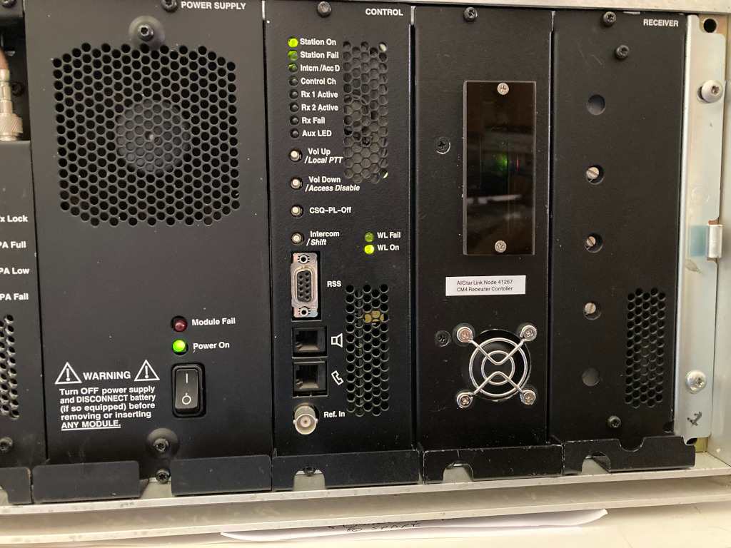
This setup works great, looks neat, and saves a rack space or two. 14 volt DC is available from the 100W Quantar, and could easily power the controller. But in our application, we have a APC 8 port IP power switch in the rack, and wanted be be able to power down or reboot the Pi separately from the repeater. The CM4 runs nice and cool in it’s new home.
The Pi is normally is powered 24/7, but since this is a backyard repeater, a cron job controls a 40A rated SSR that is driven by a CM4 GPIO pin to turn off and on the Quantar’s AC power at midnight and at 07:00 respectively. These times can be easily overridden with out of band control using Zoiper on a cell phone. The Asterisk AllStar installation also has a SIP connection over the LAN to another Asterisk box that runs a VOIP phone system at the QTH. A dial plan has been configured to allow any house phone to dial into the repeater controller and send AllStar commands including a streaming mode that allows monitoring of system audio and PTT for TX. So a QSO can be held using the phone handset and it’s DTMF pad.
Dave, K7DMK