A recent trip to the repeater site was completed to take care of a few details after the initial install. The temporary low capacity backup battery was replaced with a proper one. A Deka Fahrenheit series 140 AH AGM battery was installed. Over a hundred pounds worth of battery is now connected to the Magnum Energy inverter-charger and should provide a minimum of 12 hours of 90/10 service down to 60%-70% depth of discharge.
A second task was to switch the DMR side of the system from Brandmeister master server 3102 to 3103. Ping testing showed about 10ms less latency to the CA based server. Packet loss has been minimal. The master server URL is a parameter that can’t be changed remotely with RDAC.
RF performance is still being evaluated in different parts of the East Valley, metro Phoenix, and beyond , but so far it looks very good. Because of mountains to the South of the site, coverage is compromised toward 180 degrees. This is predicted from modeling, and confirmed by a recent trip to Tucson. Coverage was also compared to other UHF repeaters at the same location, and was as expected. The goal was to have a solid signal in the East Valley including Mesa, Gilbert, Chandler, Tempe, Scottsdale and the Eastern half of Phoenix. This appears to have been largely achieved, but testing will continue. Mountains are both a blessing and a curse, depending on whether you are on the top or bottom, and on which side of them you find yourself. Because of our topography, shadowing of a few areas is inevitable. Commercial services like public safety employ multiple sites to minimize this problem.
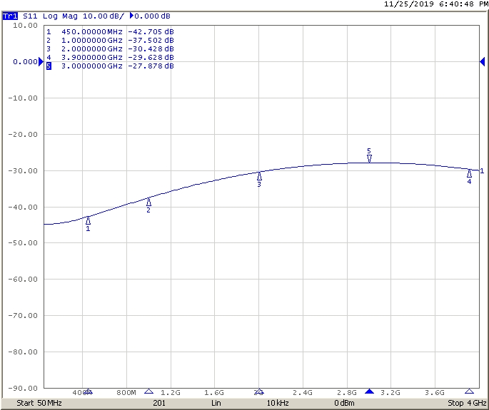
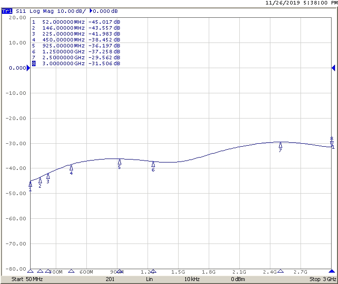
Setting a balance between RX and TX range of a repeater is always a compromise. It depends on your target audience; are you looking for HT coverage or mobiles? Is it a 10W, 25W or 50W mobile? Etc, etc. I modeled using a 10W mobile with a unity gain antenna at 1.5M height on Radio Mobile to predict coverage. Not quite an HT, but not a 50W mobile station with a 6 dB colinear either. So anything more is gravy. Is it an Elephant or an Alligator? Not sure yet, but I might be able to make the ears a little larger; I have a 10 dB attenuator between the preamp output and RX input. Whether the extra gain would be helpful is questionable. No plans on adding a power amplifier though. 40W from the TX and 20W to the antenna should be enough RF for the desired coverage area.
Just a few items are left to be done. The most significant is a method of remote battery state monitoring. The charger in the Magnum Energy unit is fully automatic. It does bulk charging at 30A max and then switches to float. It would be nice though, to be able to check on the battery from time to time. The company does offer a way to read the SOC of the battery over IP, but it’s an expensive solution. An alternate way using the RasPi AllStar controller with an A/D converter will be implemented instead.
Dave, K7DMK