In the last installment we discussed generative AI from a theoretical standpoint. I suggested it may have some utility in Amateur radio. So how?
Well let’s ask an AI chatbot. How about Perplexity for a start..
Question: How can AI be useful in Amateur Radio?
Response: (Copied and Pasted)
The integration of AI and Amateur Radio is still developing. While many of these technologies are being adopted through external software and services rather than directly built into transceivers, advances in cloud connectivity and hardware will likely increase their direct integration in the future.
AI can be highly useful in Amateur Radio (ham radio) by automating tasks, enhancing signal processing, improving prediction accuracy, and supporting both beginner and advanced operators. Key applications include noise reduction, signal analysis, smarter logging, propagation forecasting, troubleshooting, and educational resources.Detailed examples of AI’s usefulness in Amateur Radio include:
Automatic Signal Processing: AI can analyze and filter radio signals in real time, helping operators efficiently find and tune the right frequencies, especially in crowded band conditions or during contests.
Noise Reduction and Interference Mitigation: Machine learning algorithms can remove unwanted band noise using neural networks, making communications clearer and more reliable.
Propagation Prediction: AI can analyze vast amounts of historical and real-time data (like solar activity and time of day) to give more accurate and personalized predictions for when and where radio signals will propagate best, helping operators plan contacts more effectively.
Voice Recognition and Control: AI-driven voice recognition enables hands-free equipment operation and can convert text to speech or vice versa, improving accessibility for users with disabilities.
Automated Logbook and QSO (contact) Management: AI can automatically log contact details, organize QSO records, and provide operator performance analytics.
Troubleshooting and Technical Support: AI-powered tools can guide operators through repairs or optimizations, assist with antenna design, explain complex concepts, and offer tailored advice—even for newcomers studying for licensing exams.
Contest and DX Cluster Assistance: AI can analyze real-time data to recommend rare stations to contact during contests, and suggest optimal strategies to maximize scores.
Remote and Automated Operation: AI allows remote station setup and can automate routine tasks like antenna adjustment, enabling operation from anywhere with internet access.
CW (Morse Code) Decoding: AI is particularly promising for decoding Morse code (CW), especially given its ability to learn from diverse sending styles and tempos.The adoption of AI in Amateur Radio is poised to enhance efficiency, accessibility, and enjoyment for users while preserving the hobby’s innovative spirit. Not a bad answer. But there are many more. Like antenna design, troubleshooting, including circuit analysis and schematic interpretation and the list goes on.
Remember though, this technology is in perhaps the 2nd or 3rd inning. There are some inherit limitations of transformer based generative AI. Besides being limited by the training data used, there is another issue that remains somewhat illusive; so called “hallucination”. That means AI can makes things up that are not true (with great authority)! We have all known people like that. If you can’t produce that facts, baffle them with BS..
Depending on the underlying model used, there may be limitations. Particularly when it comes to math and calculations. Some models are better than others in this regard. The bottom line is always double check. If you are making an antenna designed by AI, get a second opinion. Try another AI chatbot, try another model. etc. Like the old carpenters rule: measure twice and cut once.
With all the AI hype in the News, you would think it can do just about anything. Like many people, I gave the free version of ChatGPT a whirl. Yes, it was impressive. I threw a variety of topics at it from chemistry, physics, literature, electrical engineering, RF topics like VSWR and even had it tell me a few jokes. It’s early in the ball game, but it’s already pretty impressive.
As you may know, everything you type on ChatGPT becomes public information. That information is used to help train the LLM (Large Language Model) running in the background on the supercomputer cluster. Not a big deal for guys fooling around and asking silly questions. But what about a company working on proprietary products or processes. Like drug development or R&D of an important product yet to be patented? Or even an engineer or consultant working on a pet project at home, who wants to keep prying eyes away.
Well, that where self-hosting your own version of a ChatGPT-like environment on your own local network would be great. It’s possible now, and doesn’t require a supercomputer. I first read about this possibility over a year ago. There are some open source software projects now, along with some powerful pre-trained LLM’s available for free.
It’s actually pretty amazing. Companies like Google, Meta and others have spend millions of dollars and many months of compute time creating and training these models. Their inputs consist of vast amounts of data scraped from the web. Places like Reddit and other online forums to get an understanding of language including slang. Factual sites, online sales sites, on and on it goes. All of this gets tokenized into numerical representations by a process called a transformer, a deep learning architecture, which further converts this data into vectors using a what’s called a multi-head attention mechanism. If it sounds complex, that’s because it really is. But get from this that the hard part is creating, training and encoding these models. That’s where the heavy lifting is. That’s where the supercomputers are needed along with GPU’s like the H100 from NVidia. They run up to 8 of these monsters chips on a giant heatsink. Each draws up to 700W of DC power. And they have racks of them. These GPU’s excel at doing matrix arithmetic and massively parallel tasks. They have thousands of compute cores and huge bus bandwidth. That’s what it takes to make these models.
And the incredible thing is you can download them FOR FREE. Decoding the information from these models is not trivial either, but it’s doable on a home setup. How much you have to spend depends on how fast you want the data. These models typically are contained in one large file. That’s what’s downloaded. Once you have this file, no Internet connection is needed. People confuse the idea that GPT works like a search engine; that data is being looked up on the Net as needed. That’s not how it does it’s thing. Not even close. Everything is contained in the model. Nothing is looked up live from the Internet. Nothing goes out and nothing comes in. It does not work like a typical database either. The way information is obtained in the decoding process is complex and fascinating.
So how do you do it, and what can you do with it? What the hell does this have to do with Amateur Radio you ask? Well we will get to that.
We have established a new EVAR talkgroup on the TGIF DMR network. The new TG is 21212 (I like palindromes)
It is active now, and open to anyone who likes technical discussions about Amateur Radio, electronics, time or volt nuts stuff, etc. No politics or religion please.
The current Raspi shortage shows no signs of abating soon. Several interviews with Eben Upton, head of the Raspberry Pi Foundation, recently suggested that things may get better toward the end of the year for hobbyists. Right now, most of the production of Pi 3, PI 4 and CM’s is going to industrial customers. Looking on rpilocator.com paints a fairly dismal picture, unless you’re looking for a Pi Zero.
If you are hoping to build a new AllStar simplex or duplex node, you will be disappointed when it comes to finding one of your main ingredients.
One option is to go to everyone’s favorite auction site and pay about 150 to a “Pi Scalper”. But there may be a better solution, depending on your particular application.
If a “Pi Hat” hotspot configuration such as a SHARI is desired, obviously a proper Pi SBC is clearly needed. However, if an external USB radio interface like a URIx or a Repeater Builder RA series is planned for your node, some other very good options are available.
Small, low power X86 based “Micro PC’s” are inexpensive now days, even if purchased new or renewed. Amazon and other online stores have several to choose from about $100 and up. Machines like the Lenovo ThinkCentre M700, M900, HP EliteDesk 600 and 800 models, as well as the Intel NUC series are all good candidates. Used units are even less. You might even have one stored in the closet.
Another effective, but more expensive solution, is a 1U rack mount mini-server like those made by SuperMicro. I used an Atom 330 powered version of one these running the Acid AllStar disto, for several years. It required about 30-35W of power though. Suppose a rack mount machine is not needed or wanted, still other possibilities are available in the X86 world.
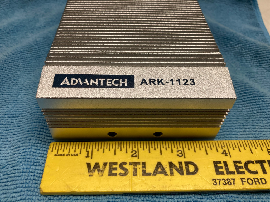
If well sited high profile AllStar repeater is being contemplated, something more reliable and more efficient than a consumer PC might be preferred. My personal favorites are small industrial computers designed for automation, digital signage and CNC. There are several companies that make these boxes, but the big player here is Advantech. These are highly reliable computers designed for 24x7x365 use in rugged environments. Many are fan-less and use high quality parts like monolithic ceramic capacitors instead of crappy Chinese electrolytic caps. The newer ones use low power multi-core CPU’s like the Intel Atom and Celeron designed for laptops. Most have industrial temp and shock ratings and exude quality when you hold one in your hands. They are built to last and generally support Linux well.
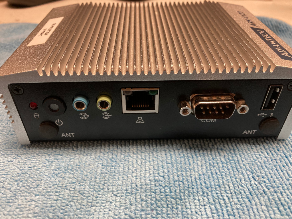
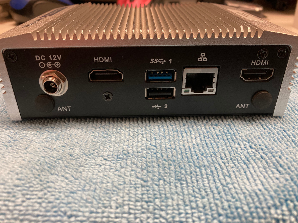
Keep an eye out on Ebay for these computers, They are expensive when purchased new, but can be had for pennies on the dollar as technology rapidly changes in industry. Advantech’s ARK series is a good example of what to look for. Some can be be found for less than $100 on Ebay. I have personally used the ARK-1123H and 1124 industrial PC’s running Debian OS AllStar 2.0 Beta 3-6, with excellent results. These computers have J1900 or N3550 multi-core processors, 4 to 8GB of DRAM and real solid state drives, not SD cards for storage. As far as compute power, they run the pants off of any Raspi available, including the CM4. Both the 1123 and 1124 are small, fairly low power (about 8-10W vs about 5W for a PI4), have no fans or other moving parts, and are fully shielded in a metal case with a effective heat sink. They are pretty small; about 13x9x4 cm. and run on 12VDC at a couple of amps, making them easy to integrate into a typical repeater system. The 1123 has 2 USB 2.0 and 1 USB 3.0 ports, 2 HDMI video ports, a RS232 serial port, 2 gigabit Ethernet NICs, and build-in sound. With ferrites added on the USB and DC power cables, the system is electrically much more quiet, from an EMI standpoint, than a Pi in a plastic box. They are robust little computers that are up to the task, look the part, and instill some confidence at a repeater site.
Our original AllStar link controller used a 1u rack mount mini-server utilizing a dual core Atom CPU and a SSD. It was running the Acid Linux distro based on CentOS. The radio interface was a DMK Engineering URI. Also mounted in the rack was a pull out LCD monitor keyboard mouse. It worked OK for several years, but Acid/CentOS 5.xx is getting long in the tooth, with no current support.
We experimented with Raspberry Pi based controllers starting with the Pi2. The audio was a sometimes a little choppy compared to the Atom CPU. With the advent of quad-core Pi’s that problem went away completely. For quite awhile, we ran a Pi3B+ in a 3D printed case sitting on top on the Quantar card cage along with the URI and cables. It worked, but wasted rack space and the Pi ran pretty hot.
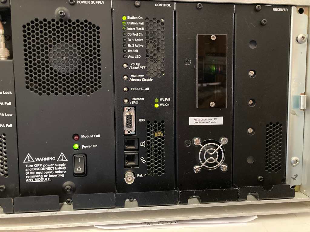
Looking at the 70cm Quantar one day, it was realized there was a nice place to put an AllStar controller behind the blank filler plate between the receiver and system control module. In the 800/900 MHz machines this slot is often occupied by a high-stability frequency reference. On other bands, occasionally, a secondary receiver is installed in the space for special applications, or perhaps a SAM (station access module). In the 450 repeater we have, it’s empty.
We had been evaluating some of the new CM4 compute modules from the Raspberry Pi Foundation mounted on their CM4-I/O board. This setup has several advantages when building a repeater controller. One problem with the standard Pi is the fact that you need access to 3 of the 4 sides of the board for connections and SD card. It becomes an unwieldy porcupine making it difficult to neatly mount in a rack case, particularly if you need external connections to the I/O. A nice thing about the CM4-I/O board is all the connectors including the microSD, are on the back edge.
The CM4 modules snap on to the I/O board in a parallel fashion using 2 low profile 100 pin PCB-PCB connectors. This is big change from the older compute module 3’s that plugged in using an edge connector like a memory DIMM. The CM4’s are available in many models with varying amounts of DRAM, with/without WiFi/Bluetooth, and eMMC flash storage. They all share the same form factor and are interchangeable and therefore upgradeable. The CPU of the CM4 is a faster quad-core@ 1.5GHz BCM2711 vs the 1.2 GHz SOC of the regular Pi4. There is one downside of the official Raspi Foundation CM4/IO board arrangement. Much of the available bus bandwidth is channeled to the single lane PCIe expansion slot present, this eliminates the USB 3.x connections as compared to the Pi4. In this application it does not matter. The URI, and all the other AllStar radio interfaces so far are USB 2.0 only, AFAIK. The sample rates used for ROIP audio simply does not require USB 3. There are other third party CM4 I/O boards available that lose the PCIe slot and offer the bandwidth to USB 3.x connections. But again, not needed here.
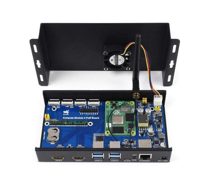
WaveShare makes a very nice all-metal case that fits the I/O board with the installed CM4 module. It has a CPU fan to cool the processor and is inexpensive. Ideal for this application. The added RF shielding is also welcome. The Waveshare CM4 version of an IO board (not used in this project) is shown mounted in their case in the photo below. The small green solder mask PCB is the CM4 compute module. This particular CM4 variant has the Wifi/Bluetooth module as well as eMMC onboard.
If USB 3 is really needed, this I/O board has it instead of PCIe. There are more and more versions of these CM4 I/O boards becoming available. The Raspberry Pi Foundation has made the design open source along with the PCB files. Custom spins of the board can be made pretty quickly.
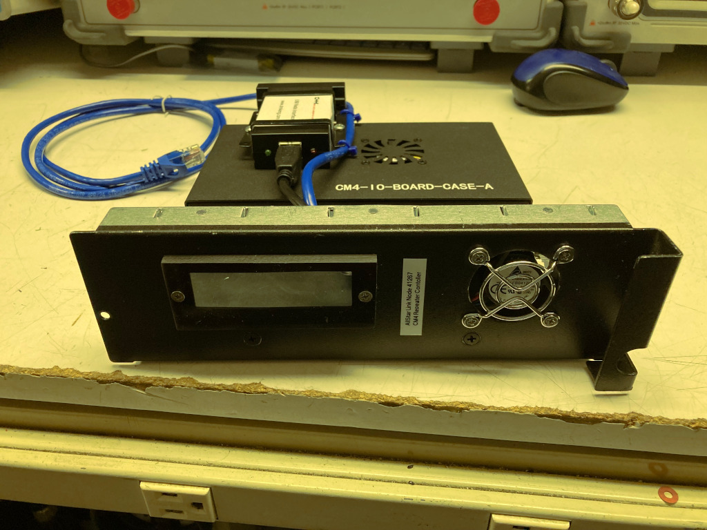
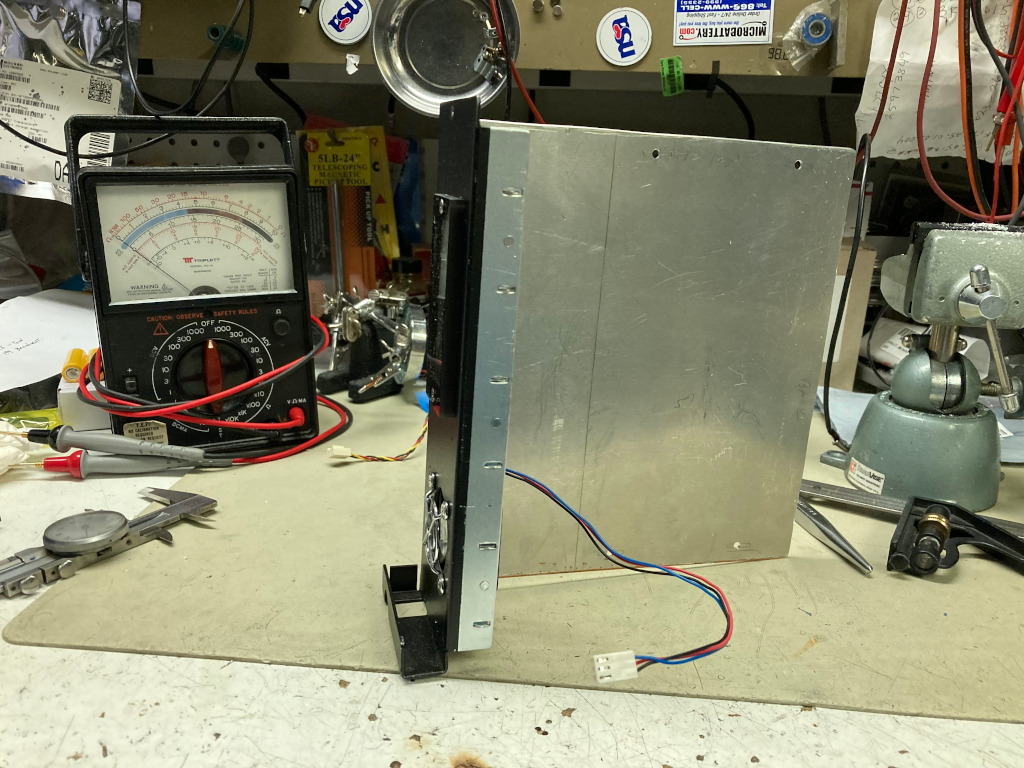
To build our new controller, we started with a blank Quantar cover plate from eBay, some 0.062 aluminum sheet, aluminum angle, and scrap plexiglass. A 1GB CM4 module with 8GB of eMMC flash and no WiFi was selected, and AllStar installed on the eMMC drive. The CM4 module was mounted on the CM4-I/O board which in turn was installed in the WaveShare case. A few 5/8 holes were punched in the side of the WaveShare cover for added air flow, and a bracket was fabricated to hold the URI to the top of the case. There is just enough clearance inside the repeater for the URI to be stacked on the WaveShare enclosure when it’s mounted to the aluminum plate.
Mechanically, the aluminum plate is cut to just under 8.25 inches high and mounted to the blank cover plate with 1/8 x 1/2 aluminum angle. The assembly slides into the card cage just like an official Moto module. A 40mm cooling fan with a finger guard is mounted in the cover plate. A small Plexi window with a cutout was installed to allow observation of the LED’s on the I/O module and URI. The WaveShare case and URI are positioned so their LED’s face forward. The URI to repeater, cat5 Ethernet, and DC power cables pass out through an opening in the rear of the card cage. The CM4-I/O board has a build-in switching regulator to allow 12 volt operation. We are using a fairly reliable PhiHong brand 2.5A 12V cord lump supply for controller power. The I/O board can also be setup to do POE if desired. As an aside. we have found over the years that these AC switching adapters are NOT all created equal. Many, many are unsafe, unreliable garbage with terrible components, poor performance and bad construction. Failure rates typically are very high, even after just a few months of use, and some pose real safety/fire hazards. Higher quality units are made by I.T.E., Meanwell, PhiHong, Delta, Panasonic, Sony and a few others. They cost more, but are worth it in the long run.
This setup works great, looks neat, and saves a rack space or two. 14 volt DC is available from the 100W Quantar, and could easily power the controller. But in our application, we have a APC 8 port IP power switch in the rack, and wanted be be able to power down or reboot the Pi separately from the repeater. The CM4 runs nice and cool in it’s new home.
The Pi is normally is powered 24/7, but since this is a backyard repeater, a cron job controls a 40A rated SSR that is driven by a CM4 GPIO pin to turn off and on the Quantar’s AC power at midnight and at 07:00 respectively. These times can be easily overridden with out of band control using Zoiper on a cell phone. The Asterisk AllStar installation also has a SIP connection over the LAN to another Asterisk box that runs a VOIP phone system at the QTH. A dial plan has been configured to allow any house phone to dial into the repeater controller and send AllStar commands including a streaming mode that allows monitoring of system audio and PTT for TX. So a QSO can be held using the phone handset and it’s DTMF pad.
Selecting a GPS receiver for use as a NTP server reference involves some trade offs. It can be a deep rabbit hole with seemingly no bottom if you just start studying spec sheets.
I believe the first step is define the role of the server and needed vs desired accuracy on your real network. My goal was 1 millisecond time with sub 500 microsecond jitter / wander. Remember that network traffic and congestion in network devices like switches can have impacts greater than instability of the time source. So some extended ping testing under varying network conditions can be helpful to get an idea of network induced error. Looking at standard deviation of ping time is one good indication of problems to be solved before proceeding.
Assuming your goals are relatively modest like mine and the network checks out OK, the next step is finding a suitable GPS receiver.
A few things we are looking for here are: Standard NMEA 183 output, 1 PPS output pulse and serial rather than USB interface. Provision for an external antenna is a great feature and may be a requirement depending on the situation. Although a USB interface may sound good, because of the way communication is achieved by asynchronous polling of the host device, a lot of uncorrectable variability occurs compared to old-fashioned RS232 serial, even at low baud rates like 4800. I haven’t actually evaluated USB and what this means from a practical standpoint, however. The PFSense document on NTP does not recommend USB.
GPS receivers can be divided into two broad classes with some crossover. Most receivers are position/navigation optimized devices. But there are those that are designed specifically for timing applications. Navigational units need to deal with triangulation from multiple sats at different elevations and also with motion. Their algorithms have location parameters as their priority which slightly degrades timing accuracy. Timing GPS receivers are different. They can go into a “position hold” mode at previously established coordinates and even look at just one satellite to achieve very low jitter on the 1 pps pulse. The internal circuits including the clock oscillator and those that process the pulse are also optimized so that 10-15 nanosecond specs are typical of this class. About 10 to 100 times better than your average navigation GPS. These are probably overkill for a home lab though. They tend to be expensive ‘niche” devices. Another class of receivers from the innovative U-Blox people have part numbers that end in “T” like 5T 0r 6T. The T stands for timing, and they are a hybrid design that combine good positional performance, but can go into position hold and behave as very accurate timing receivers. They use an internal TCXO rather than a regular crystal oscillator for better hold-over stability.
Thus far, I have evaluated three receivers and compared their relative NTP performance on PFSense. One was already in stock and the other two were purchased.
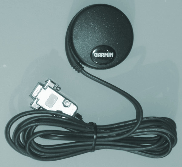
The first RX was a CSI Mini-Max, a marine oriented unit with WAAS and differential GPS capability, but no pps output. The second was a Garmin GPS18x-LVC, a hockey-puck style OEM 12 ch receiver with a built-in patch antenna, WAAS, and PPS pulse output. The third was an inexpensive U-Blox 6M module modified to generate PPS from it’s blinking LED and it’s 3.3V logic i/o converted to RS232 by way of a Max3232.
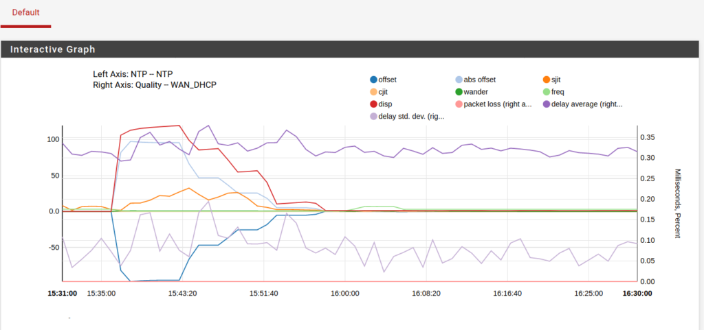
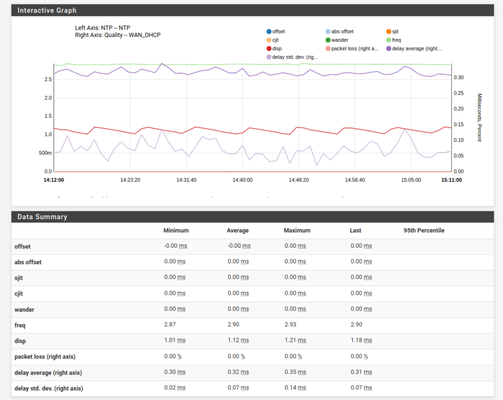
All performed well enough in a home lab, for all but the most critical applications. That said, the addition of the 1 pps pulse makes a significant improvement. See the graph below. It shows the Garmin unit running without the PPS signal line connected in the first portion, and the effect of connecting the PPS line toward the mid-portion of the graph. Jitter, wander and dispersion all decrease dramatically.
Adding PPS to NMEA Data Stream
The Garmin 18x is a very good performer. It had adequate sensitivity to pick up 8-10 sats indoors. A real achievement with the foil-backed insulation in the ceiling. It’s also very convenient to use. It has standard RS232 serial output, and just needs 5V at about 60 mA; that can be robbed from a nearby USB port. I have it sitting on the top of my 6ft rack staring up towards the roof. It also has a handy magnet on the bottom to hold it to ferrous metal.
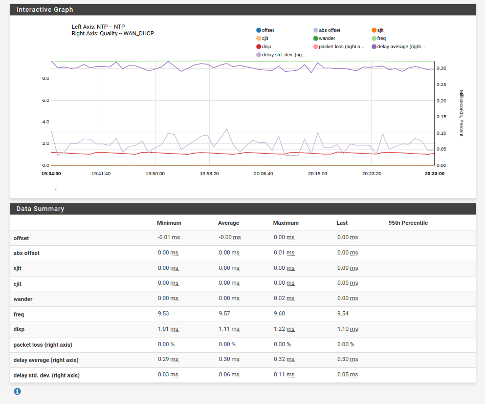
Garmin GPS18x-LVCGarmin 18x NTP Performance over 1 hour
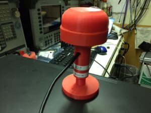
Finally, the little U-Blox 6M also worked very well. Maybe just a bit more jitter at times than the Garmin, but still well within my design goals. Again, this was indoors. It was eventually assembled in a 3D printed PETG case that can be mounted outdoors with a 20M length of shielded Cat5 cable carrying both the serial data and 5v power. A modified RJ45 to DB9 adapter inserts the power at the computer end of the cable. The base has screw holes to fasten to a flat surface. The UBlox people have a very nice piece of software (Windows only) called U-Center that allow many, many different parameters to be changed and saved to flash in these modules. I merely set the baud rate, turned on the PPS LED and set it’s duty cycle, but there are a lot more options to explore here. I might have missed something really good…
Neo 6M StatsMini Water Tower with UBlox 6M insideCat5 to DB9 data and power
Next NTP experiments may be using a Raspberry Pi4. I also have a U-Blox LEA-5T based surplus timing board coming on a slow boat from China (literally) It’s a GPS/GNSS module optimized for timing applications. It has the fixed position mode available and can use a single satellite. Should be interesting to compare and program with U-Center. More fun to come.
The kernel used in Linux and BSD operating systems has historically derived it’s timing accuracy from an oscillator, normally an inexpensive crystal oscillator present on the system board. From this oscillator, all the system clocks needed for the CPU and various buses are generated. In addition, most computers have a real time clock chip (RTC) powered by a battery that keeps time in non-volatile ram. This clock is often synchronized with NTP and OS time as a start-up process. Early NTP clocks concentrated efforts solely on providing more accurate and stable system oscillators.
More recently, many Unix-like kernels have included a mechanism for disciplining it’s timing by an outside reference. Most modern implementations of Linux and BSD have this feature. This allows very fine adjustment of kernel timing and subsequent time keeping without having to make hardware modifications to the system board. The NTP server software, likewise has an internal timing module generally based on a modeled PLL oscillator, that allows external references of both NMEA time data and precise 1 pps time pulses to be applied. The combination of kernel disciplining and external references for NTP allow very accurate time information to be served.
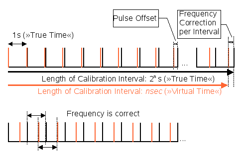
PPS Correction
Two interesting software distributions that can used to create Swiss-army knife network appliances for firewalls/UTM’s, routers and VPN gateways are PFSense and OPNSense. Both have the ability to provide a highly accurate NTP time server, when locked to an external reference, in addition to many other network tasks. So in this case, a dedicated computer is not needed exclusively for a NTP server.
In the first experiment, an existing installation of PFSense currently acting as a firewall and VPN gateway was modified to add an accurate, low latency NTP server to the LAN. The PFSense software is running on a small rack mount SuperMicro mini-server with a dual core D525 Atom CPU. It’s an ideal machine for this purpose since it has an unused serial port and requires less than 25 watts of power to operate. It’s LAN side is already connected to the network by a Gigabit NIC. The NTP server will be setup to allow time requests on the LAN port only.
In part 3, we will discuss the considerations of selecting an appropriate GPS external reference, and the kind of results one might expect with various classes of GPS receivers.
NTP is an old, but still very useful time transfer protocol. The mechanism uses NTP client software on a host computer that “asks” for time info, and a NTP server somewhere out on the network that sends out the current time and date in a specific format. “Out on the network ” usually means the Internet. Usually port 123 is used. There are many existing public NTP servers on the Internet and many are incorporated into open pools like pool.ntp.org that permit a generic url to be specified rather than a particular IP address.
So why build a NTP server and put it on your local network? If very accurate time is needed for your application, such as scientific experiments, time stamps in synced databases or radio systems, etc, a local time server can be very useful. Because of the variable latency of WAN based servers, really accurate time is hard to achieve via the Internet . The actual network time delay accessing a Internet server has some compensation in the protocol, but it’s the unpredictable jitter (phase noise being a model) and wander (random noise) due to the vulgarities of the Internet, that is not correctable.
Time servers are described by their “Stratum level” determined by their source of time reference, and also how far they are removed from the primary reference. A Stratum 1 NTP server gets it’s time from a so called primary time reference called a Stratum 0 (zero) source. So by definition, there is no Stratum zero NTP server, since the clock does not connect directly to a network. Twenty years ago, building a Stratum 1 NTP server meant using something like a very expensive cesium clock, or perhaps one based on a rubidium oscillator. Today, GPS can provide that reference with comparable specs, but as usual, the devil is in the details. More on that later.
Another time server that connects to the Stratum 1 time server to get it’s time to forward, becomes a Stratum 2 server by this convention. Still another NTP server that connects to the second server would become a Stratum 3 server. Each time you are farther removed from the primary time source, the Stratum level goes up. The accuracy and uncertainty gets worse each time because of the expected jitter in the network connection between them is accumulating.
Not long ago, establishing a true Stratum 1 time server on one’s network was an expensive proposition. Today we have several relatively inexpensive options to choose from.
We will be exploring a couple of these options over the next few weeks.
Little projects have a habit of growing into more complicated endeavors. As mentioned in a previous post, it was thought that a simple remote monitoring system for the backup battery and repeater environmental conditions would be a useful addition.
It was decided that battery voltage, DC supply voltage, battery temperature and ambient (cabinet) temperature would adequate. A small DAQ hung off the Pi3B+ being used as the AllStar controller with 10-12 bits resolution should do the job.
A little research revealed inexpensive ADS1115 4 channel I2C bus A/D converter boards that were available for less that ten dollars. These can operate on either a 3.3 or 5V single rail supply, require just two I2C connections to the Pi’s GPIO bus, and offer 16 bits (15 bits + sign bit in single-ended mode) of resolution. These boards were designed with the Arduino in mind, but they work just fine on the Pi as well. Sample code in both Python and C was available as a starting point for the software end. A couple of boards were ordered.
As far as temperature measurement, 3 terminal band-gap sensors like the LM35 and TMP series (TMP35,36.37) are easy use and require no calibration. They operate on a single 5V supply and output a voltage linearly proportional to temperature in degrees C. Several TMP37 sensors were purchased. These measure temps from 5C to 150C and output 20mv/degrees C. Just measure the output voltage and divide by 0.02 and you have the temperature in Centigrade degrees.
The ADS1115 has an internal programmable gain amplifier that allows scaling the input voltage range. This setting, along with the the supply voltage (5V or 3.3V) determines the full scale value (for a 32768 count) of the converter. It was decided to use a 5V supply and 0-4.096V full scale for the best noise immunity. A 10:1 input voltage divider built with a few precision resistors would allow 0-40V DC voltages to be monitored. Because the Pi I2C bus uses 3.3V logic levels and the ADS1115 is powered by 5V, a level translator is included in the design to insure compatibility without having to modify pull-up resistors.
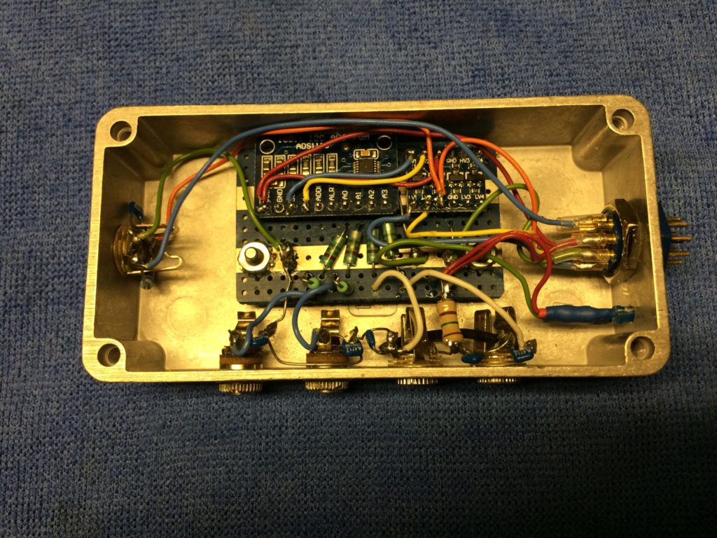
A prototype was assembled in a die cast metal box for shielding. LC low pass filters were incorporated on each input using 0.5uH RF chokes and 470 pF ceramic caps to minimize RF ingress. Sample software was modified for some testing. It was set up for two voltage channels and two temp channels on the four inputs available with the 1115 ADC.
The two voltage channels worked great. The resistors in the voltage divider present a moderate 200K input resistance and were hand-selected within about a few tenths of a percent. The readings are formatted in the software for two decimal places as in “13.45”, and the measured voltage closely agreed with a 4-1/2 digit multimeter. A little UHF RF was sprinkled in the vicinity with a HT, and all was well. Voltage measurements: done.
The temperature channels were a different matter, however. It turns out the TMP37 sensors are exquisitely sensitive to RF. Thus began the long saga. I tried just about every RF trick in the book to tame these sensors. The manufacturers’ datasheet recommends a 0.1uF ceramic cap from Vcc to ground. In high noise environments they also suggest adding an additional 1-5uF tantalum cap in parallel. RF ingress at various frequencies vs noise is not specifically addressed in the datasheet. I tried those suggested caps, and several other bypass capacitor combinations with disappointing results. A 4 watt 70cm HT set to 1 watt on 446 MHz was used as the test transmitter. With the prototype sensor isolated on the bench, transmitting from 3 meters away would upset the reading by the equivalent of several degrees C. At closer range, the reading were less than plausible and clearly in error with ridiculous values. It was obvious the band-gap diode in the sensor made a dandy detector and was rectifying the RF and causing a DC offset. Back to the drawing board.. Round two explored shielding; this included installing the sensor in a closed-ended brass tube with a well shielded connecting cable wrapped in copper tape at the entrance of the tube. Better, but still not good enough. I have had radio receivers that were less sensitive to RF than these sensors!
Round three added UHF rated ferrite beads to the Vcc and output leads of the device . Slightly better still, but the repeater site is a very high RF environment and my confidence was low.
PLAN B: After some discussion, a friend suggested trying a 1 wire temperature sensor. I thought that they likely used a diode type sensor, and just have an internal A/D and 1 wire interface. Might have the same RF issues as the 3 wire sensors that are driving me crazy.
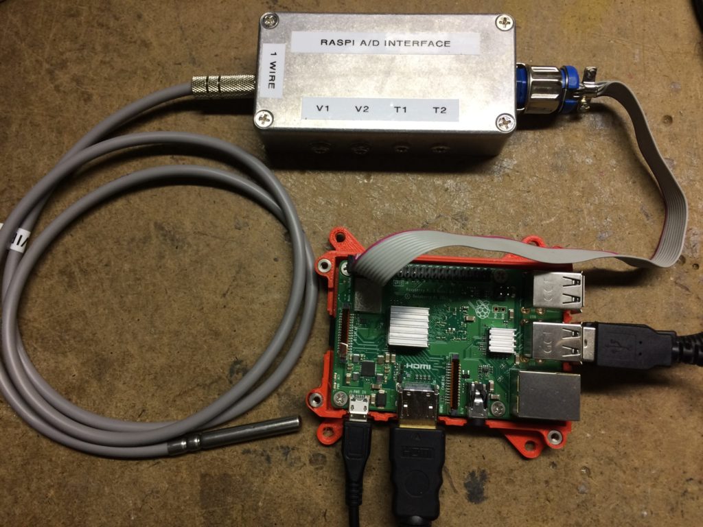
Two very nice 1 wire stainless steel temp probes with silicone wire leads were ordered from Jeff B. (Amazon) as a trial. The 1 wire GPIO kernel driver was loaded on the Pi and some new software coded. When the probes arrived, expectations were subdued, but the tests proceeded. Amazing. These things seem to ignore RF; even at close range. Even TX at 4W power from the HT at less than 1 meter distance was OK. Problem is most likely solved. A new hole for another jack was drilled in the die cast box to accommodate the new 1W temp probe. Luckily, there was a spare wire in the cable available to make the connection to GPIO #4 on the Pi.
Thanks to some ideas gleaned from a sample script written by WA3DSP, I was able to pipe the output from the compiled C binaries that read the voltage and temp data into the AllStar TTS voice synth. Some custom ulaw sound files were created that say things like “the battery voltage is”, “the battery temperature is” and a few others. Now, on demand, with a DTMF commands over AllStar, spoken battery voltage and temp, supply voltage, and ambient temperature readings can be executed.
Next step is to make a trip to the site and do the physical install. A longer connecting cable to the Pi’s GPIO bus was constructed to replace the short test cable. Plan is to mount the A/D box in the rear of the cabinet about 75 cm from the Pi. How long can you go with a I2C bus signal? Well I found a nice paper on that. It depends on the clock speed of the bus. The speed can vary; typically from 10K to 1M baud. At the default 100K speed, the main limiting factors are capacitance to ground and termination resistance. With the standard Pi hardware, a good rule of thumb is 500 pF max on the capacitance. I used 6 conductor foil shielded cable 75cm long. It measured an average of 180 pF from any conductor to the foil shield, and about 100 pF inter-conductor. So this length should be fine. I didn’t dig out the scope and look at rise and fall times yet, but if I2C errors are noticed the clock rate can easily be decreased with a config.txt argument. More clamp ferrites were added to the connecting cable to keep away evil spirits. BTW, If really long distances are needed, special I2C transceiver driver chips are available. They are used on both ends of the long interconnect.
EPILOG: As a final TMP37 temperature sensor experiment, a new (last!) configuration was tried. A small, fully shielded aluminum box was liberated from the junk box. A piece of proto PCB was used to mount the sensor along with more 0.5 uH LP/470 pF cap filters in the Vcc and output leads. Three bypass caps were installed close to the leads on the device, along with the ferrite beads. The sensor was taped to the bottom of the box with aluminum tape to thermally bond and electrically double-shield the device itself within the shielded enclosure. Finally, a double shielded 3.5mm plug to 3.5mm plug cable, again with a ferrite, was used to make the connection to the A/D box. Yes, it mostly works with RF. If one gets the HT antenna within about 25cm of the connecting cable, it starts to affect the reading slightly. But that’s a really strong field. I’m going to try this sensor for ambient temperature at the site and see how it works. It’s optional, and not a critical reading. If the TMP37 proves useless at the site, and the ambient temp parameter proves valuable, plan C will implement another 1 wire sensor for this reading as well.
Yet another interesting part that I may try for ambient measurements, which is inching it’s way to me on a slow boat from China (eBay), is the Bosch BME280 combination temp, barometric pressure and humidity sensor with I2C and SPI bus interfaces. We don’t really need the additional parameters, but why not? RF stability? Who knows. It’s in a tiny metal can, so maybe.. Update in a few months when they finally arrive.
As a point of reference, I had a package out for 84 days from China recently. Ordered on Feb 26, and arrived today 5/20. A lot of low priority freight that normally used air transport is being sent by sea due to the pandemic.
Many DMR radios have a hidden feature that allows a user to enter a “service menu” through a series of key presses that offers a few features helpful for troubleshooting and adjustments. Both Motorola XPR gen 1 and gen 2 series radios as well as Hytera HT’s and mobiles have this facility.
One of the functions present in this service menu is RSSI , or received signal strength indicator. This gives you a fairly accurate ( to be determined), way of measuring RX signal strength in dBm. A kind of a poor man’s measurement receiver. An alligator meter for a repeater transmitter, you might say.
As far as the elephant part of the equation, the live Brandmeister last heard list can display the measured RSSI value reported to their network by Hytera and Moto repeaters receivers. Sounds like an elephantometer to me.
So by monitoring the RSSI values from the rig and from the last heard simultaneously, what we have is a way to compare RX vs TX performance of a repeater from a particular location. We can use either a HT or mobile radio for the test, and evaluate the performance at a variety of remote TX power levels.
The accuracy of these RSS indications is somewhat unknown without additional measurement verification, but that’s pretty easy to do. Just put your rig into the service mode, display RSSI and feed in a calibrated signal generator, and see what it reads. Similarly, a measured DMR signal, from say a HT with an attenuator, connected directly to the repeater RX input will give a known RSSI value to be compared to the reading on the last heard. Ideally, a couple of power levels should be checked on both the subscriber radio and repeater.
Some initial trials on the new K7EVR machine look promising as being a valid measurement technique, but calibrated tests have not been performed yet. The results will be updated here, if significantly different. As an example, using a MD782G mobile radio programmed for low power (5W), a quarter-wave vertical antenna @ 4M AGL, and a distance of 11 KM (LOS), the RSSI values were within about 3 dB of each other, with the RSSI from the repeater TX being the better number. That seems to indicate the ears and mouth are about the right size for say a 10-15W mobile station.